Schematic cross-section of the example of two insulated wires in free space.
This example comprises two wires in a circular shield (twinax). In this example the dielectric material inside the shield is frequency dependent. No Laplace solver is used for the Spice simulation or the analytical simulation. For further explantation of the terms used please refer to the User and Theory manuals.
Schematic cross-section of the example of two insulated wires in free space.
1. Launch the SACAMOS SW1 application.
2. From the file menu chose 'Select MOD' to browse to an existing cable model directory or 'Create MOD' to create a new one. Here we have created a new MOD directory called 'MOD_WEB_EXAMPLES'. Note: that all MOD directories have to reside in the root of the SACAMOS folder.
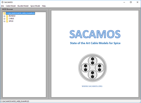
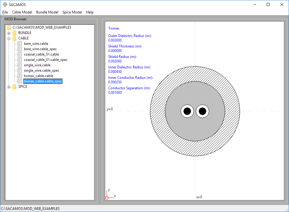
3. Once MOD has been selected the main GUI window will look like:
4. The other menus on the toolbar will now be enabled.
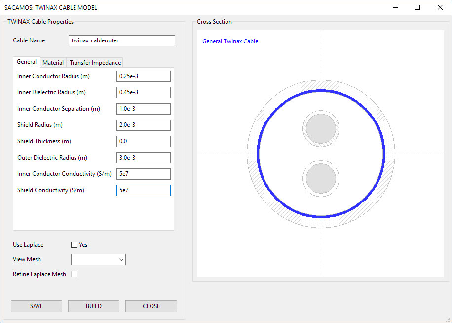
1. From the 'Cable Model' menu chose 'Twinax Cable'.
2. Enter a name for the cable model e.g. twinax_cable
3. Now enter the parameters for the cable model, note all dimensions are in meters (m) and can be in floating point or scientific (E) notation :
inner conductor radius = 0.25e-3
inner dielectric radius = 0.45e-3
conductor separation = 1.0e-3
shield radius = 2.0e-3
shield thickness = 0.0
outer dielectric radius = 3.0e-3
inner conductor conductivity = 5e7
shield conductivity = 5e7
.
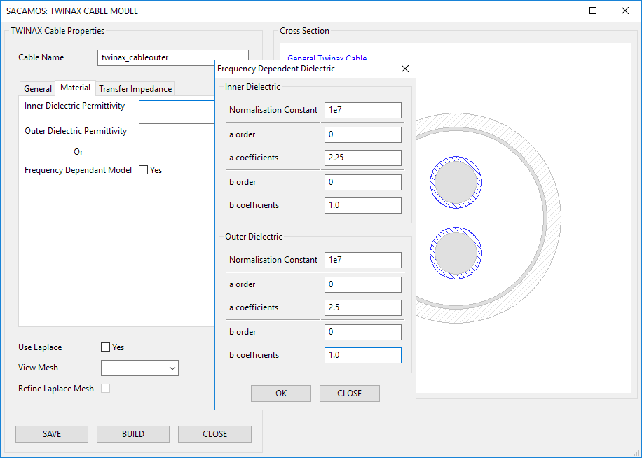
4. To enter the frequency dependent parameters, select 'material' tab and 'tick' the check box and a pop-up window will appear. Enter the following parameters:
Inner dielectric permittivity model:
normalisation constant = 1e7
a order = 0
a constants = 2.25
b order = 0
b constants = 1.0
Outer dielectric permittivity model:
normalisation constant = 1e7
a order = 0
a constants = 2.5
b order = 0
b constants = 1.0
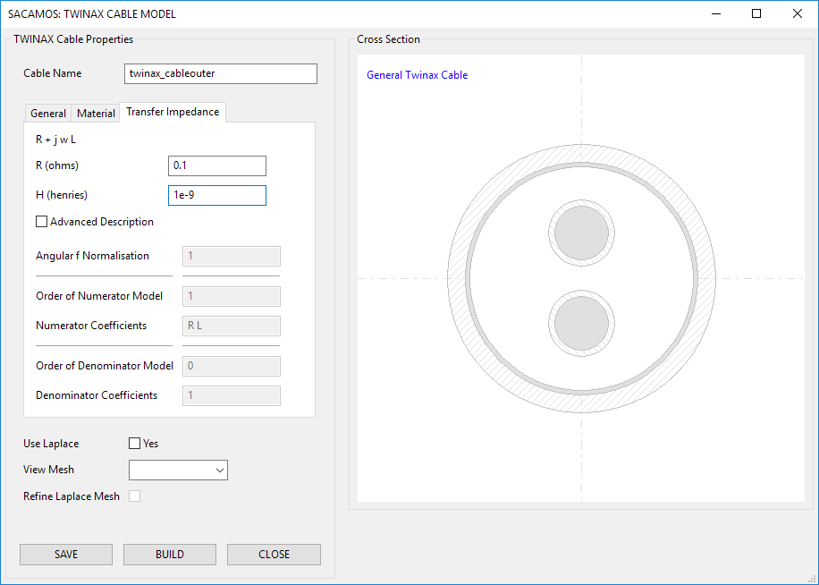
5. Select the 'transfer impedance' tab to define the transfer impedance:
R = 0.1
L = 1e-9
6. Click 'SAVE'. If all is correct, the save button will be disabled. Then click 'BUILD'.
7. The Run Satus will appear and state that the cable model builder finished correctly.
8. Close the cable model window..
Even though a spice model is required for just a single cable it must first be created as a bundle. Therefore:
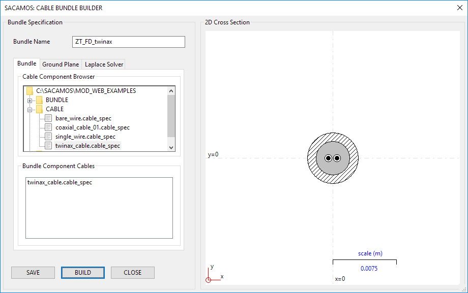
1. From the 'Bundle Model' menu chose 'Create Bundle'.
2. Enter a name for the cable bundle model e.g. FD_ZT_Twinax.
3. Expand the 'Cable' directory on the 'Cable Component Browser'.
4. Double click the 'twinax_cable' cable in the component browser and enter the required x and y coordinates of the cable's centre (and rotation if appropriate) and click 'OK' to place the cable. Place the cable in the centre of the cross section i.e. x = 0.0, y = 0.0 and rotation = 0.0.
5. Click 'SAVE'. If all is correct, the save button will be disabled. Then click 'BUILD'.
6. The Run Satus will appear and state that the cable model builder finished correctly.
7. Close the cable model window.
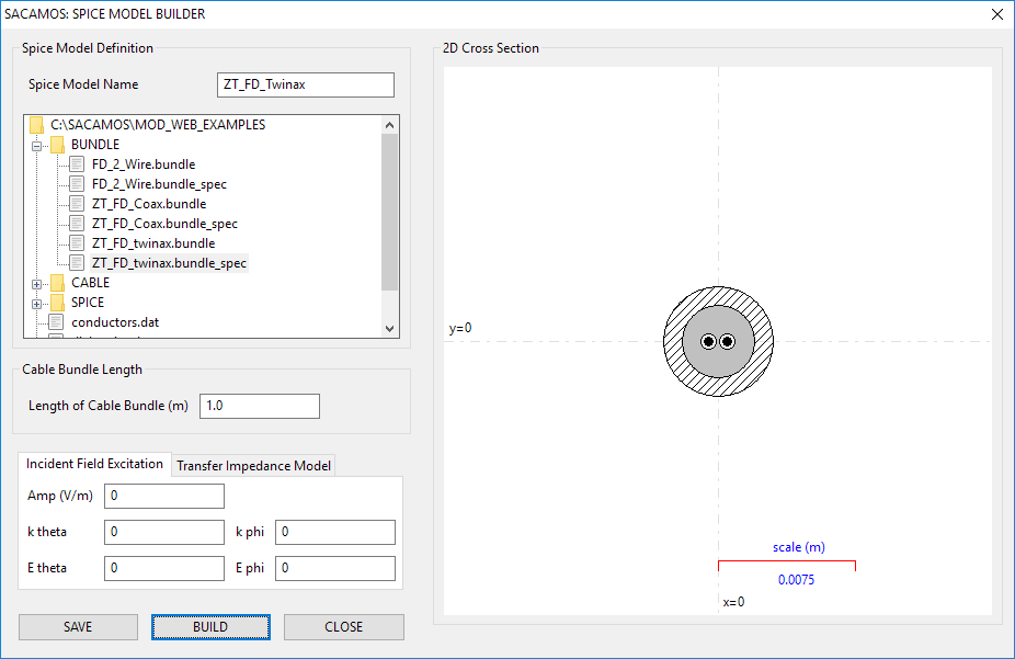
1. From the 'Spice Model' menu chose 'Create Spice Model'.
2. Enter a name for the Spice model e.g. FD_ZT_Twinax.
3. Expand the 'Bundle' directory in the file browser and select the bundle for which the Spice model is required by double clicking on the '.bundle_spec' file. The schematic will then be displayed.
4. Enter the lenght of cable that the model will represent, in meters, e.g. 1.0.
5. No more details are required for this model. Therefore click 'SAVE' and then 'BUILD'.
6. The Run Satus will appear and state that the Spice model builder finished correctly.
7. Close the cable model window.
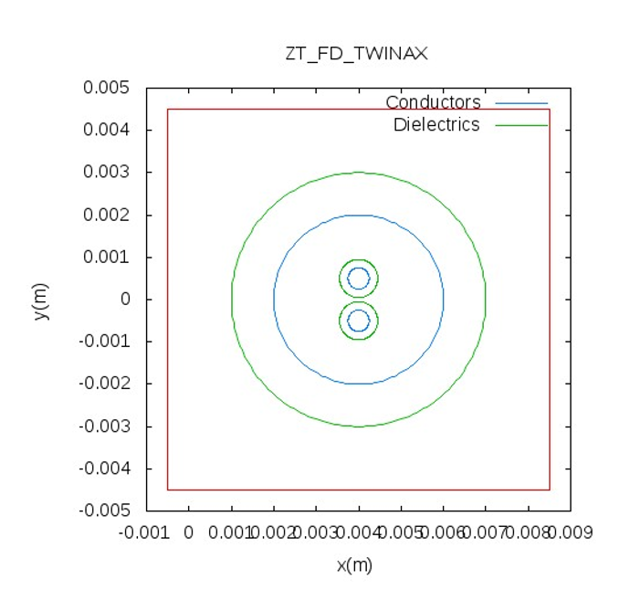
1. From the main SACAMOS GUI. Expand the 'Cable' and 'Bundle' branches of the 'MOD Browser'. There should be entries for the cable and bundle models created above.
2. Double clicking the 'cable_spec' entries will display the cable or bundle. For cables the relevant data will also be displayed.
Spice models have now been created for NGspice, LTspice and Pspice, along with symbols for NGspice and LTspice. These symbols now need to be placed in the symbol folders for the schematic capture being used. For the example that follows this will be gschem, part of the gEDA suite which requires the '.sym' file.
Note only the symbol files need to be exported the associated ',lib' files remain in the MOD folder and must not be moved as the locationof the .lib file is encoded in the .sym file.
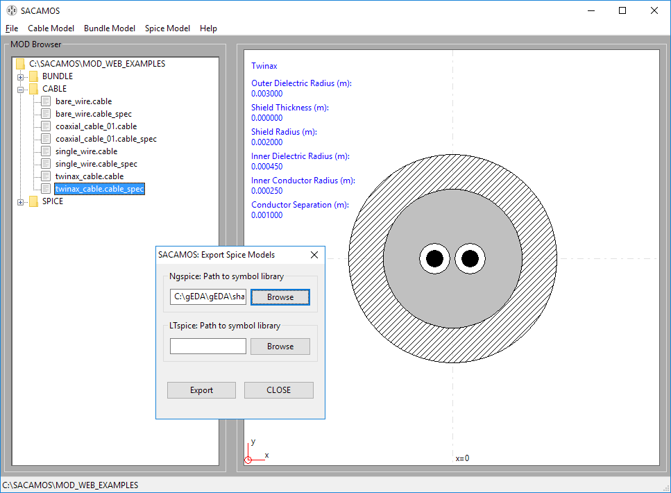
1. From the 'Spice Model' menu chose 'Export Spice Model'.
2. From here browse to the symbol folders for the schematic capture system you are using. For example for gschem installed in the root directory of a Windows system the path is: 'C:\gEDA\gEDA\share\gEDA\sym\local'
3. Click 'EXPORT'
4.Click 'CLOSE'. The symbols can now be used in the schematic capture porcess...